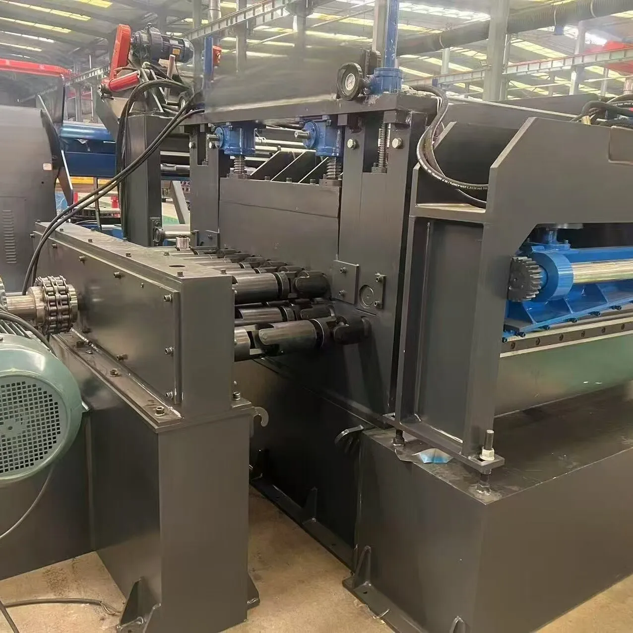
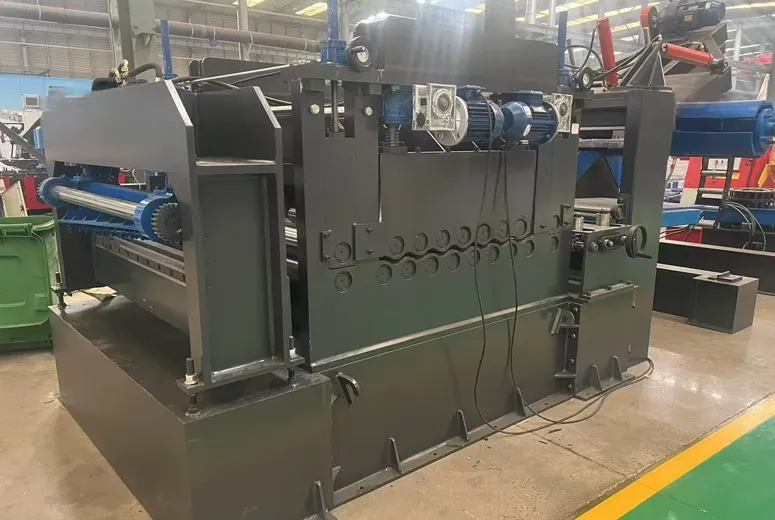
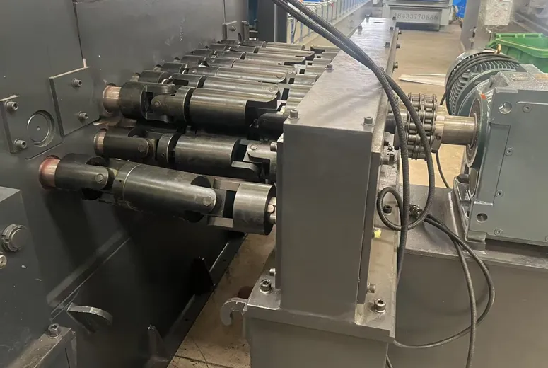
I.Composed devices
|
No |
Name |
Quantity |
|
1 |
Hydraulic entry coil car |
1set |
|
2 |
Hydraulic de-coiler |
1 set |
|
3 |
Leveling and cutting machine |
1 set |
|
4 |
Hydraulic system |
1 set |
|
5 |
Electrical control system |
1 set |
II.Technical Parameter
1.Material: Carbon steel
1.1.Plate thickness: Iron plate 1.0-6.35mm
1.2.Board width 500~1219mm
1.3.The inner diameter of the coil is Φ 508mm
1.4.The outer diameter of the coil material is ≤ Φ 1600mm
1.5.The maximum weight of the coil is 15T
2.15T hydraulic decoiler with trolley
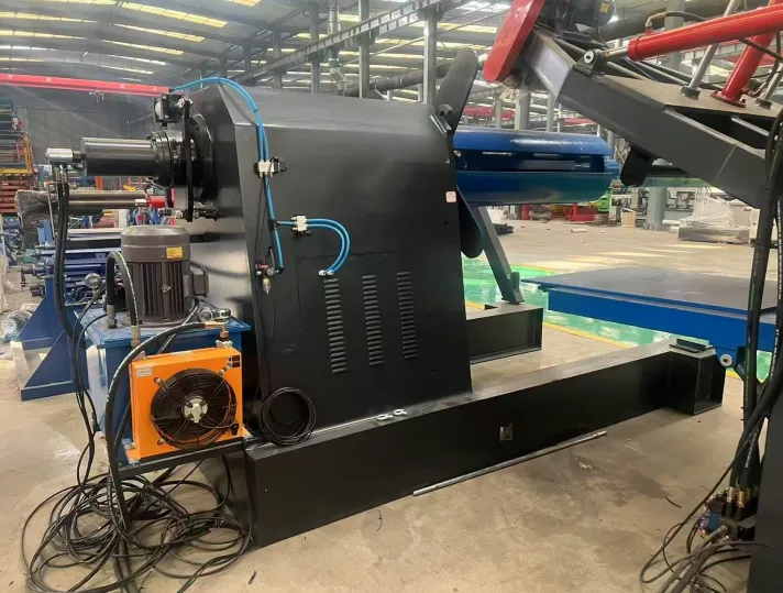
Loading trolley
2.1.Purpose: Position the coil set on the unwinding machine drum.
2.2.Structure: Ground mounted.
2.3.The lifting rack is a V-shaped structure, driven by oil cylinders for lifting and guided by four column guides.
2.4.The car disc is driven by a hydraulic motor and moves along the steel rail.
2.5.Drive: Hydraulic Motor
Decoiler
2.5. Purpose: Actively unwinding or recycling coil materials.
2.6. Structure: Single drum type.
2.7. Inner diameter of coil material: Φ508mm
2.8.4 supporting drums, hydraulic expansion. Range of expansion and contraction: φ 475- φ 525mm
2.9. The drum is driven by a variable frequency motor and can be rewound.
2.10. Install a pneumatic disc brake at the end of the spindle, which can generate unwinding tension and can also be used for braking.
2.11. Install a swinging pressure roller above the drum, which rotates electrically and swings hydraulically.
2.12. Uncoiling motor: 15kw
2.13. Uncoiling frequency converter: 18.5kw
2.14. Host frame made of 400H steel
2.15. Host spindle 232 * 60 seamless tube
2.16. Uncoiler with hydraulic automatic support arm
2.17. Uncoiler with hydraulic pressure arm
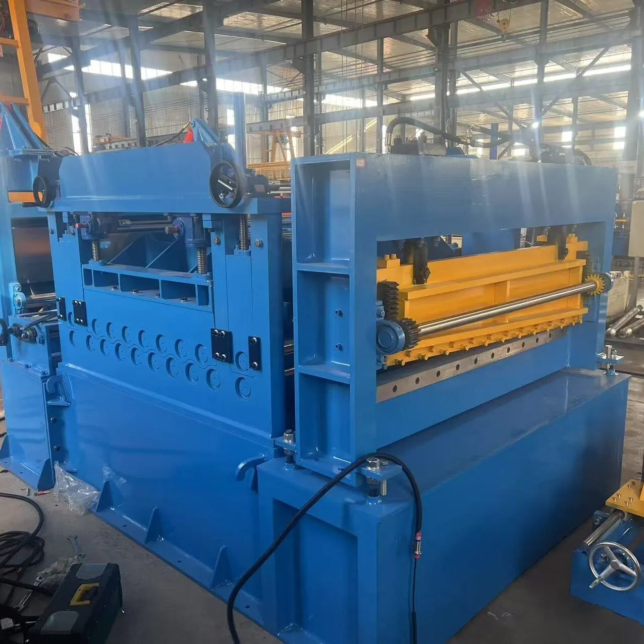
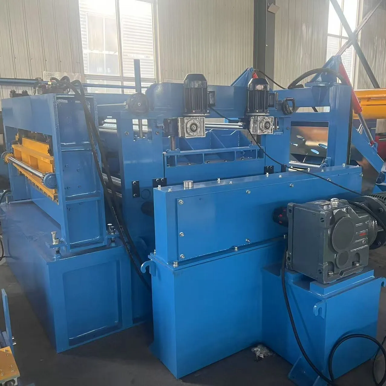
3.Leveling and cutting machine
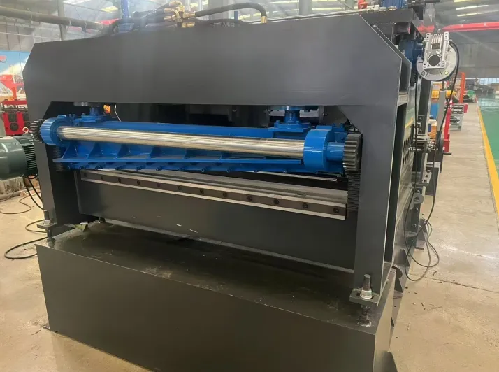
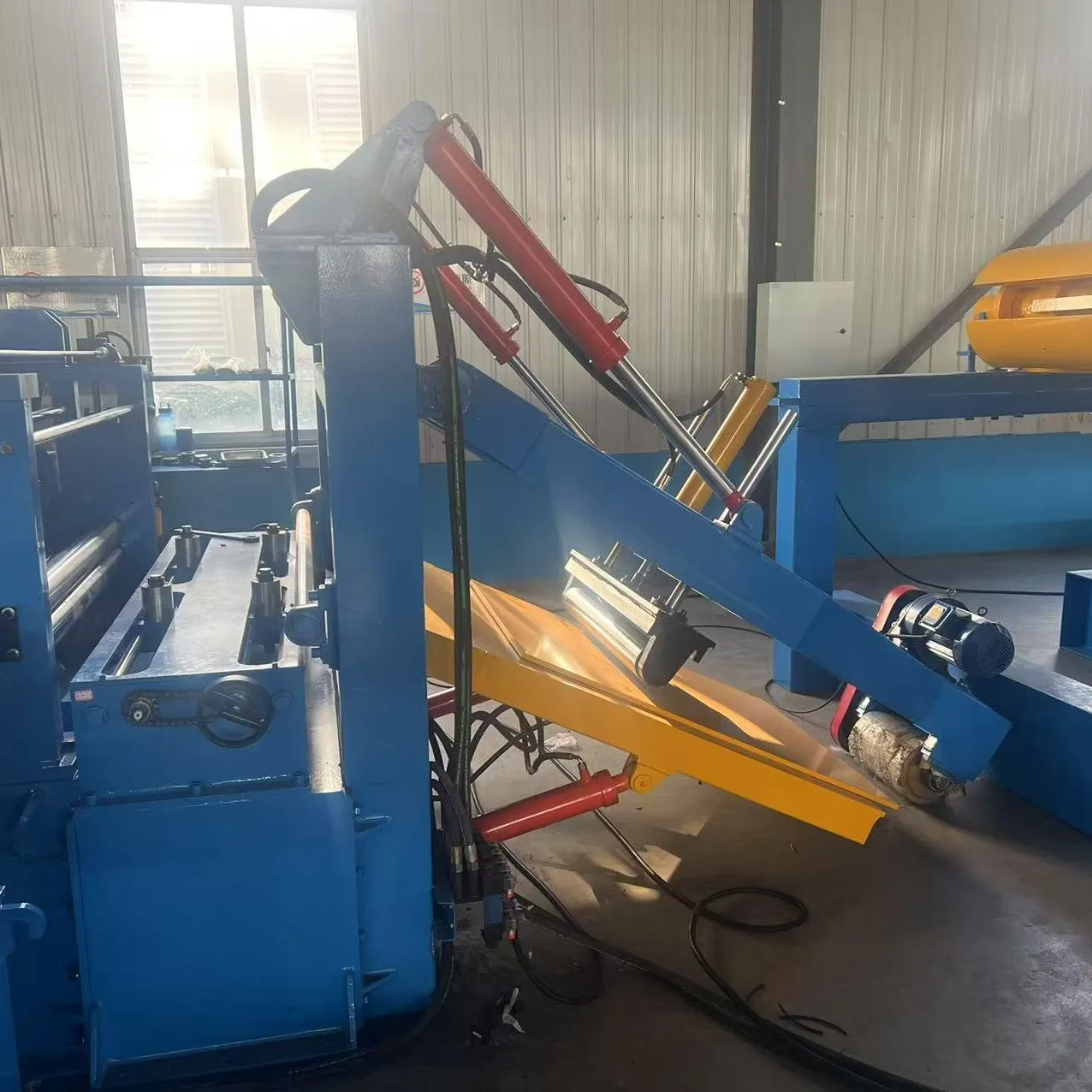
3.1.Quadruple leveling machine+shovel head
3.2.Purpose: To level the roll material
3.3.There are 15 leveling rollers arranged with 7 on top and 8 on the bottom (with two feeding shafts added), with a roller diameter of ф 115, an effective roller surface width of 1300mm, made of 40Cr material, high-frequency quenched, and coated with hard chromium on the surface.
3.4.There are 2 rows of short support rollers on top and bottom, with a roller diameter of ф 100 and a material of 40Cr. They are quenched at high frequency, and the upper and lower rows of support rollers are adjusted by inclined iron to prevent deformation of the leveling roller under stress.
3.5.The machine base is divided into upper and lower parts, connected by four strong pull rods. The upper seat is used to install the upper row leveling roller group. The lower machine base is used to install the lower leveling roller group and to support the entire machine body.
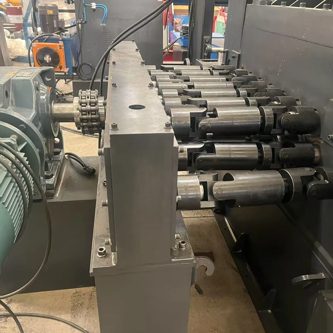
3.6.The transmission system consists of a motor, a hard tooth surface reducer, and a gear transmission.
3.7.The reducer adopts a hard tooth surface reducer.
3.8.The coupling adopts high-quality ball cage type.
3.9.Four levels of leveling machine, with two auxiliary shafts added on top and bottom.
3.10.The motor is 22kw
3.11.Frequency converter 30kw
3.12.Adding a shovel head to the leveling machine causes hydraulic pressure to rise and fall.
3.13.Shovel machine motor: 3KW motor

